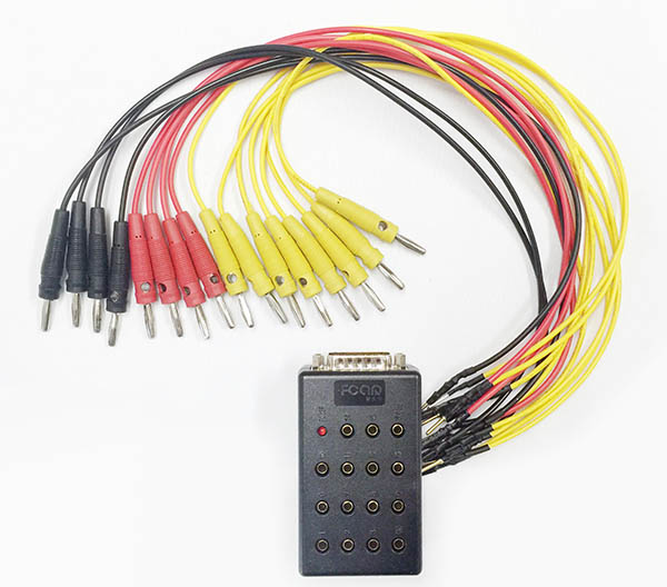
The jumper box package includes:
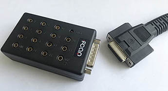
- Jumper box with 16 pin holes and DB15 port at side
- 16 cable, 4 black, 4 red, 8 yellow
Instruction (HD truck):
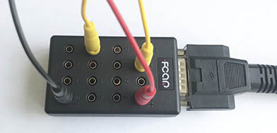
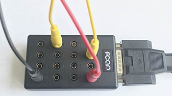
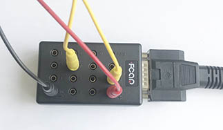
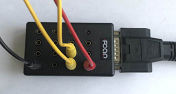
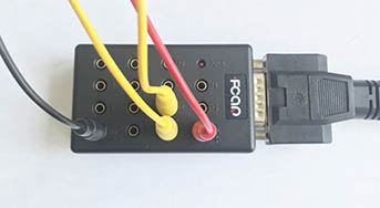
- Connect cable (black, red or yellow), one end to Jumper box pin hole, and another end to Vehicle data port, see the following step how to plug:
- Jumper cable connectivity:
- If Caterpillar engine, you can find Higher voltage around 4.5V, plug into pin hole 7 and another lower voltage around 1v and plug into pin hole 15 and use Engine Caterpillar (CDL-Cat Data Link)
- To find a pin with about 0.44V, which is 1708 Low, plug into pin hole 13, when ignition switch on
- To find a pin with about 4.46V, which is 1708 High, plug into pin hole 12, when ignition switch on
- To find a pin with about 2.4V, which is 1939 Can Low, plug into pin hole 14, when ignition switch on
- To find a pin with about 2.6V, which is 1939 Can High, plug into pin hole 6, when ignition switch on
- To find a pin with 0V and make sure this is ground, plug into pin hole GND (or pin hole 4), when ignition switch off.
- To find a pin with about 12V or 24v, which is positive power, plug into pin hole VCC (or pin hole 16), when ignition switch off.
- K-Line and L-Line: to find a pin with about 11V which is K-Line of ISO9141-2 & Keyword 2000, plug into pin hole 7, L-Line of ISO9141-2 & Keyword 2000 to pin hole 15.
- Using multimeter to measure each pin voltage in vehicle data port
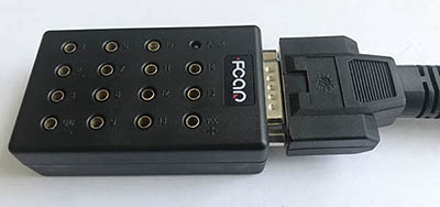
- FCAR Jumper Box
-
Pin 1 Pin 6 CAN/J1939 + Pin 10 J1850 - Power LED Pin 2 J1850 + Pin 7 K-line of ISO9141-2 & KWP2000 &CDL+ Pin 11 Pin 14 CAN/J1939 - Pin 3 Pin 8 Pin 12 J1708 + Pin 15 L-line of ISO9141-2 & KWP2000 &CDL- Pin 4 (GND-) Chassis Ground Pin 9 Pin 13 J1708 - Pin 16 (VCC+) Battery Vol V+
When you plug property cord, you might try to use Diesel OBD at first scan to see whether it will communicate and then try to use property program to scan.
CAN J1939:
CAN bus uses two dedicated wires for communication. The wires are called CAN high and CAN low. When the CAN bus is in idle mode, both lines carry 2.5V. When data bits are being transmitted, the CAN high line goes to 3.75V and the CAN low drops to 1.25V, thereby generating a 2.5V differential between the lines. Since communication relies on a voltage differential between the two bus lines, the CAN bus is NOT sensitive to inductive spikes, electrical fields or other noise.
J1708:
The J1708 bus consists of two wires (A and B) with at least one twist (360°) per inch (2.54 cm) and a total length of up to 40 m. The voltage level on the bus is determined by the difference in voltage potential between wires “A” and “B”. A logical high level (1) is achieved when point A is at least 200 mV more positive than point B. A logical low level (0) means that point A is at least 200 mV more negative than point B (See the following figure). The transceiver should be fed with +6V to (-6V) in relation to common ground (common for all devices).
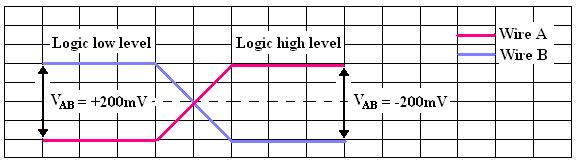
Determination of the logic bus-level.
The bus is in a logical high level when it is in idle mode, if all transmitters are deactivated or when all transmitters is sending a logical high bit (1). To place the bus in a logical low state only one transmitter has to send a logical low bit (0), which makes the logical low bit dominant.